


1. Introduction: The Critical Juncture of DC Overcurrent Protection
The facility manager’s morning inspection seemed routine—until he noticed a faint glow inside Solar Combiner Box #3. What he discovered nearly cost his company everything: a sustained DC arc, burning silently at over 3,000°F (1,650°C), had been consuming the connection terminals for hours.
The investigation revealed a common but critical mistake: an AC-rated device had been used in a high-voltage DC system. Unlike alternating current (AC), which naturally crosses zero volts 120 times per second, providing repeated opportunities for an arc to extinguish, direct current maintains a constant voltage. This relentless supply of energy creates persistent, high-temperature arcs that are exponentially more difficult to interrupt.
As solar arrays and Battery Energy Storage Systems (BESS) scale up, system designers face a crucial decision: choosing between the sacrificial, deterministic nature of DC fuses and the resettable, electro-mechanical design of DC circuit breakers.
This choice is not just technical; it is a complex interplay of system reliability and long-term financial planning. This guide dissects the decision to help you make the optimal choice for your specific application.
2. The Physics of Protection: A Tale of Two Philosophies
To make an informed decision, one must understand how the core physical principles of each device dictate its performance in the field.
2.1 The Sacrificial Certainty of the DC Fuse
A DC fuse is a single-use device that provides protection through the thermal vaporization of a precisely engineered internal element. Its operation is governed by fundamental physics, making it highly reliable.

- Physics of Interruption: When a fault current exceeds the rating, the internal element melts. Modern DC fuses are filled with high-purity quartz sand. The intense heat of the arc melts this sand into a glass-like structure known as fulgurite. This process absorbs massive thermal energy and creates an insulating barrier that rapidly extinguishes the arc.
- Energy Let-Through (I^2t): Fuses excel at limiting the “energy let-through” (measured in Ampere-squared seconds). Their ultra-fast operation limits the peak fault current, protecting sensitive downstream electronics like inverters from destructive surges.
- Predictability: The tripping characteristic is determined by the melting point of metal—a stable physical property. This makes fuses immune to the mechanical wear or electronic aging that can affect complex breakers.
2.2 The Resettable Mechanics of the DC Circuit Breaker
A DC circuit breaker is a reusable device designed to physically separate contacts to interrupt a fault. For higher current applications, these are often built as DC Molded Case Circuit Breakers (MCCB).

- Physics of Interruption: Unlike a fuse that “smothers” an arc, a breaker must actively stretch and cool it. When a fault occurs, a trip mechanism releases a latch, and springs force the contacts apart. Specialized magnetic “blowout” coils push the arc into an “arc chute,” where metal plates divide and cool the arc until it extinguishes. For a deeper dive into these mechanisms, you can refer to technical guides on circuit breaker tripping and coil arrangements.
- Trip Characteristics: Breakers typically use a thermal-magnetic mechanism (bending bimetallic strips for overload, electromagnets for short circuits). However, because these are mechanical devices, they are subject to wear, lubrication drying, and environmental de-rating—crucial factors in hot combiner boxes.
2.3 Coordination and Selectivity
Selective coordination ensures that only the device closest to the fault opens, leaving the rest of the solar array operational.
- Fuses: Coordination is straightforward using simple ratio rules based on factory-tested $I^2t$ values.
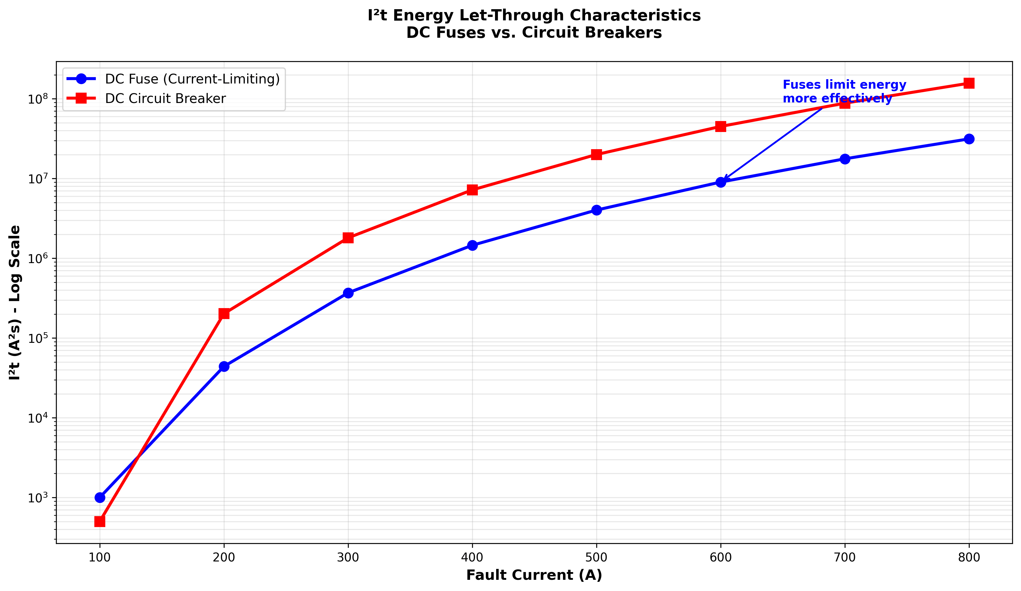
- Breakers: Coordination requires overlaying Time-Current Curves (TCCs). This can be complex due to the tolerance bands of mechanical springs and the impact of ambient temperature.
3. Economic Modeling: Total Cost of Ownership (TCO)
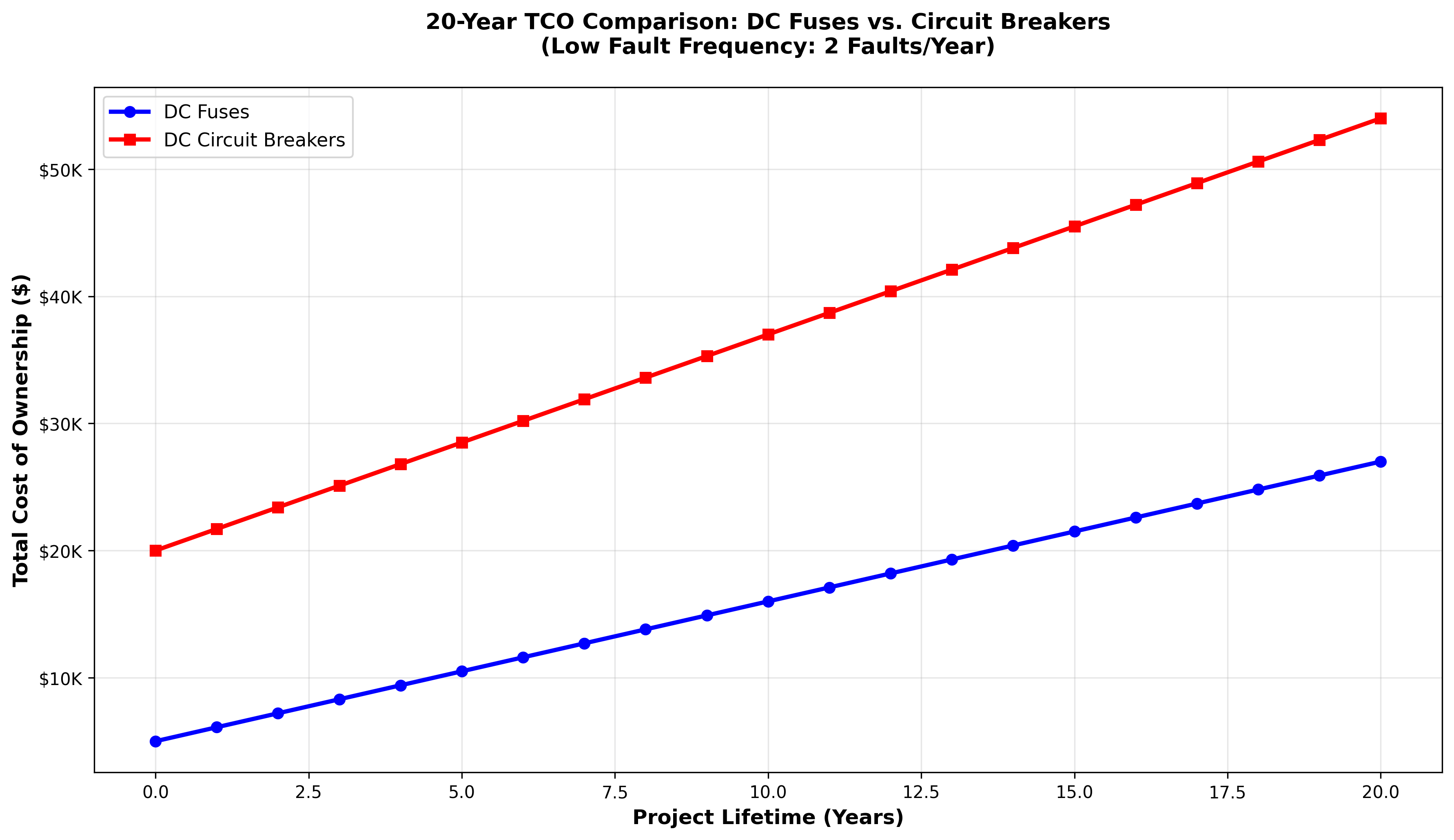
For procurement managers, the choice often comes down to the spreadsheet. A TCO analysis over the 20-year lifespan of a solar project reveals significant differences.
3.1 Capital Expenditure (CapEx)
The initial investment heavily favors fuses. A high-quality DC fuse and holder can be 5 to 20 times less expensive than a comparable DC circuit breaker or MCCB.
| Component | Typical Unit Cost (Fuse) | Typical Unit Cost (Breaker) |
|---|---|---|
| Device | 5−20 | 50−250+ |
| Hardware | 10−30 (Holder) | Included |
| Total (per circuit) | 15−50 | 50−250+ |

In a utility-scale project with thousands of strings, the CapEx savings from using fuses are substantial.
3.2 Operational Expenditure (OpEx)
OpEx offers a nuanced picture.
- Fuses: Have zero maintenance costs but incur a cost per fault (replacement part + labor/truck roll).
- Breakers: Require periodic testing and calibration (e.g., per NETA standards) but have a low cost per fault (simply resetting the switch).
3.3 The Cost of Downtime
- C&I Solar: Downtime results in lost energy revenue. If maintenance can be scheduled, the financial impact is manageable.
- Mission-Critical: In data centers or off-grid sites, downtime is catastrophic. The cost of an outage dwarfs the equipment cost.
The Verdict: In scenarios with low fault frequency (a well-designed system), DC fuses generally offer a lower 20-year TCO. Breakers typically only break even financially in environments with frequent nuisance trips or high labor costs for site visits.
4. Reliability and Safety Engineering
Beyond economics, this is a risk management decision.
4.1 Failure Mode and Effects Analysis (FMEA)
An FMEA comparison highlights the risk profiles. According to studies on Failure Modes and Effects Analysis (FMEA), mechanical complexity introduces more potential failure points.
| Device | Primary Failure Mode | Severity |
|---|---|---|
| DC Fuse | Open (Safe Fail): Fatigue from thermal cycling. | Low |
| DC Breaker | Fail to Trip (Danger): Mechanical binding or contact welding. | High |
Fuses tend to fail “open” (safe), while mechanical breakers have a risk of failing “closed” (dangerous), especially if contacts weld together during a high-current event.
4.2 Personnel Safety and Lockout-Tagout (LOTO)
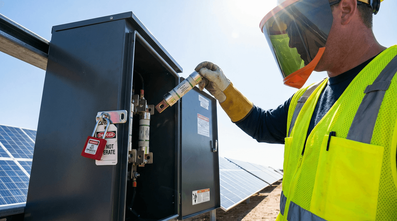
Safety officers often prefer fuses for isolation. A visibly open fuse holder—where the fuse is physically removed—provides an unambiguous air gap. A circuit breaker handle in the “OFF” position relies on internal mechanics that cannot be seen; if the contacts inside are welded shut, the circuit is still live.
5. Decision Framework: Making the Choice
The optimal choice depends on your specific application scenario.
Scenario A: Commercial & Industrial (C&I) Solar
- Priorities: ROI, Low CapEx, Scheduled Maintenance.
- Recommendation: Favor DC Fuses.
For C&I projects, the significantly lower upfront cost of fuses drives a better ROI. Maintenance is usually outsourced and can be scheduled, mitigating the inconvenience of fuse replacement.
Scenario B: Mission-Critical Applications
- Priorities: Uptime, Absolute Protection Certainty, Safety.
- Recommendation: Favor DC Fuses.
In critical infrastructure, the “resettability” of a breaker can actually be a liability. Resetting a breaker into a hard fault can cause an explosion. The forced downtime of a fuse ensures a technician investigates the root cause. Furthermore, the physics-based reliability of a fuse is preferred where failure is not an option.
Scenario C: Remote Sites with High Nuisance Trips
- Priorities: Avoiding Truck Rolls, Remote Resetting (if motor-operated).
- Recommendation: Favor DC Circuit Breakers / MCCBs.
If a site is difficult to access (e.g., mountain tops) and prone to non-damaging surges, the higher cost of a breaker is justified by avoiding expensive travel for repairs.
6. Conclusion
There is no single “best” solution, but there is a “most appropriate” engineering choice.
- Choose DC Fuses for maximum reliability, safety, and cost-efficiency in standard solar applications.
- Choose DC Circuit Breakers or DC MCCBs for applications requiring frequent switching, immediate resetting convenience, or where site access is severely restricted.
By looking beyond the datasheet and considering the total lifecycle cost and safety profile, engineers can design systems that are robust, safe, and economically optimized.
5 Image Generation Prompts
Here are the prompts to generate high-quality, relevant images for your blog.
1. Featured Image (Top of Article)
- Prompt: A photorealistic, cinematic shot of a solar combiner box interior, slightly open, revealing high-tech electrical components. One side features sleek modern DC fuses, the other side features robust DC circuit breakers. The lighting is dramatic, highlighting the copper terminals and engineering details. High contrast, professional industrial photography style.
- Alt Text: Interior of a smart solar combiner box comparing DC fuses and DC circuit breakers.
2. Section 2.1 (Physics of Fuses)
- Prompt: A 3D cross-section diagram of a cylindrical DC fuse. Inside the fuse, show high-purity white quartz sand surrounding a silver melting element. A small, contained, glowing orange arc is being extinguished by the sand, turning it into glass (fulgurite). Clean, technical illustration style, white background.
- Alt Text: Cross-section of a DC fuse showing quartz sand extinguishing an electrical arc.
3. Section 2.2 (Physics of Breakers)
- Prompt: A detailed technical macro shot of a DC circuit breaker’s internal mechanism. Focus on the metal arc chutes (splitter plates) and the separation of copper contacts. Blue electrical sparks are visible between the contacts, being stretched into the chute. Engineering visualization, blue and metallic tones.
- Alt Text: Internal mechanism of a DC circuit breaker showing arc chutes and contact separation.
4. Section 3 (Economics/TCO)
- Prompt: An isometric 3D vector graphic on a clean background. A vintage balance scale. On one side, a small stack of gold coins labeled “CapEx” (representing Fuses). On the other side, a larger stack of coins labeled “CapEx” (representing Breakers). In the background, a line graph shows cost over time. Business infographic style, minimalist.
- Alt Text: Cost comparison infographic showing Capital Expenditure differences between fuses and breakers.
5. Section 4.2 (Safety/LOTO)
- Prompt: A professional solar technician wearing safety gear (gloves, helmet) performing maintenance on a DC combiner box. The technician is holding a removed DC fuse in a holder, creating a visible air gap in the circuit. Sunlight flares in the background. Focus on safety and clear isolation. Realism style.
- Alt Text: Solar technician performing Lockout-Tagout safety procedure by removing a DC fuse.