



Contactors and relays are electric switches used to facilitate the connection and disconnection of electric circuits. Despite being used for somewhat similar purposes, there are several distinguishing attributes between the two. For understanding contactors and relays, let’s briefly overview both working mechanisms.
Explain The Difference Between Contactors And Relays
How Do Contactors And Relays Work?
The contactors use a magnetic field generated by an electromagnet and eventually move the armatures, resulting in the circuit opening or closing accordingly. Contactors are meant to handle high currents and heavy loads like motors, lighting or heating systems.
A relay uses current to energize the coil in the relay and create a magnetic field, which is used to open or close the circuit. Relays are used for handling low currents, such as in small-scale lighting systems, safety devices, air conditioners, and other home appliances.
Relays VS Contactors
Contactors And Relays Types
Based on their functions and mechanisms, there are several types of relay and contactor, out of which the most common ones used are:
1. Types Of Contactors
- Modular Contactor(AC and DC)
- Knife-switch contactor
- Manual contactor
- Vacuum contactor
- Electromagnetic contactors
- Reversing contactors
Our extensive contactor portfolio includes specialized solutions such as AC modular contactors and DC modular contactors. For comprehensive selection guidance, explore our complete contactor types overview and learn how to choose AC modular contactors for optimal performance.
2. Types Of Relay
- General purpose relay
- Electromagnetic relay
- Solid state relay
- Step relay
- Differential relay
- Impulse relay
- Timer relay
Our relay solutions encompass various specialized types including step relays for sequential control, impulse relays for latching applications, and timer relays for time-delay functions. For comprehensive relay applications, visit our general purpose relay manufacturers guide.

Types of Relays
Difference Between Relay And Contactor
While the contactor and the relay are used for similar purposes, why are they different products? Let’s elaborate on the features based on which there is said to be a difference between contactors and relays.
Understanding contact configurations is essential for proper application. Learn about NO NC contactor contact principles and discover why modular contactors are preferred over traditional designs in modern electrical installations.
Contactors and Relays – Know the Difference and Applications
Purpose Of Installation
The purpose of installing contactors and relays in electrical systems is to ensure smooth operations with a minimum risk of damage. A contactor is installed to deal with high currents, while the relay is used for opening and closing circuits with low power. The Contactor and relay keep the circuits and equipment safe from damage. They are installed in places with the electrical setup to control devices and equipment.
Difference In Load Capacity
Relays are usually compatible enough to tolerate loads of 10 A or even less, which makes them suitable for low-power usage circuits. On the other hand, a contactor can carry a load as heavy as 10A to 1000A or even greater than it. And that is why the contactors are the perfect choice for high-power circuits.

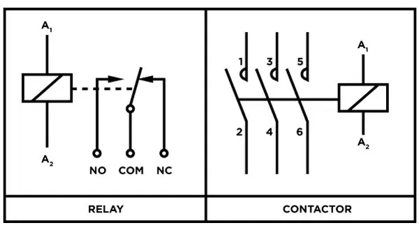
Wiring Diagram of Contactors
Different Open/Close Contact Standard
It indicates the default state of the contactor and relay. A contactor is normally open (NO) in its default stage, and there is no current flow in that state. In comparison, a relay in its de-energised state can be Normally Open or Normally Closed, depending on the usage.
Difference In Size
The size of a contactor is more extensive than that of a relay, which is small. The bigger size of the contactor is rightly justified by its capacity to handle higher loads. Similarly, the lower capacity of a relay is correlated to its smaller size.

Wiring Diagram of Relay
Durability And Longevity
The former wins the argument when the contactor and relay are compared concerning durability. The contactor is built in a way that it can tolerate larger loads for extended periods than a relay. You can switch contactors frequently millions of times without fear of any damage or malfunction. In contrast, a relay can entertain the switching less frequently and only upto a few thousand times.
Auxiliary Contacts
Contactors often come with attached auxiliary contacts. They can either be NO or NC. They are responsible for controlling the contactor and providing additional signals. An example of such contact is any indicator light when the motor is operational. Whereas, often, a relay doesn’t have any auxiliary contacts attached.
Consumption Of Power
The contactor needs more power due to the bigger electromagnet and coil used, while the relay needs less power as there is no coil or smaller electromagnet.
Cost Factor
When using contactors and relays, the contactors need you to pay more when compared with relays. The increased price is justified by the level of protection and automation that contactors provide.
Switching Speed
The switching speed of a contactor or relay is the time it takes to switch positions, from open to close or vice versa. The contactor takes around 20 to milliseconds to switch, while a relay is quicker and takes around 3 to 100 milliseconds. It is because contactors are by-built made to carry heavier loads and are slightly slow in switching, but relays are meant for lighter loads, and that is why they take less time to switch.
Safety Measurements
Due to the high capacity of the contactors to bear loads, the safety measurements they are equipped with are also higher than those of the relays. The safety level is acquired via these techniques:
Spring Loaded Contacts
The contactor disconnects the circuit completely in a de-energized state without any current passing. The springs keep the contacts apart because they are welded together. If the circuit isn’t opened properly in an overload situation, there could be a safety risk.
This feature isn’t necessary in relays since they specialize in lower current loads.
Arc Suppression
This feature is made a part of contactors as they have to carry higher than 10 amperes of load. Arc separation involves breaking up the current waves, which still try to flow when the contacts are separated.
This feature is uncommon in relays as they dont need that much safety against higher currents. The allowed load in a relay is less than 10 amperes, so there’s no need for additional safety features.
Overload Safety Feature
The feature interrupts the circuit if there is an increased current flow during a preset selected time, usually 10-30 seconds. This, in turn, provides additional protection to the equipment.
In the case of relays, this feature is generally not present.
Applications
Contacts are made keeping in requirements for a 3-phase system. For relays, the standard is set for a single-phase system. A contactor can withstand voltage up to 1000 volts, as opposed to a relay that can tolerate only 250 volts.
After delving into the differences between contactors and relays, we can gain a more intuitive understanding by watching a video. This video provides a detailed explanation of the basic construction of contactors and relays, as well as their practical applications in various electrical systems. By watching the video, you will be able to understand more clearly how these devices perform their crucial functions in circuits. Please click the following link to watch the video:
Source: @ElectricianU on YouTube
How To Make A Choice Between Relay And Contactors
The choice between relay and contactor is not based on personal preference but on several factors based on relay and contactor differences. The foremost of them is the purpose of use. You must know the type of load and current rating for that particular circuit for which the type of switch is to be used.
The frequency of switching operations is also a key point in this respect. One must know that circuits with heavy loads, high control voltage, and frequent switching will work well with a contactor. Similarly, a relay suits circuits with low power, lower control voltage and less frequent switching.
Contactor Vs Relay Vs Circuit Breaker
Points Of Difference | Contactors | Relay | Circuit Breaker |
Primary Function | Used for connecting/disconnecting high-power loads | Used for low circuit loads | |
Load Capacity | 10A to 1000A or even greater | 10 A or even less | 15A to 20A |
Manual Or Electric Control | Electric control | Electric control | Manual as well as electric control |
| Durability | More durable | Less durable | More durable |
| Contact Type | NO, and NC | NO, and NC | NC only |
| Switching Speed | Slow | Fast | Fastest |
Final Words
Contactor and relay are both essential devices for your electrical system, provided they are somewhat different despite being working as an electrical switch. They differ with respect to their capacity, mechanism and working and based on these features, have their peculiar installation areas.
Feeling at a loss about where to find the most premium quality of contactors and relays? Check out our exclusive world-class collection and get a whole new experience of reliability and expertise.
Professional FAQ: Contactors and Relays Technical Comparison
1. What are the electromagnetic design differences between contactors and relays that affect their switching performance?
Answer: Electromagnetic design fundamentally differs between contactors and relays based on their intended applications. Contactor electromagnetic systems feature high-power coils (typically 5-50VA) with robust magnetic circuits designed for reliable operation under voltage fluctuations (±15% tolerance). The magnetic core utilizes laminated silicon steel to minimize eddy current losses and features shading rings (copper or aluminum bands) to prevent chattering during AC operation. Contact force generation typically ranges 5-50N for reliable heavy-load switching. Relay electromagnetic systems use low-power coils (0.1-2VA) with compact magnetic circuits optimized for sensitivity and fast response. The magnetic path often employs solid ferrite cores for DC applications or laminated cores for AC versions. Key performance differences: Contactor pickup/dropout ratios typically 80-90%/10-20% of rated voltage ensuring reliable operation, while relay ratios are 70-80%/20-30% for higher sensitivity. Switching speeds: Contactors 10-50ms (designed for load handling), relays 3-15ms (optimized for signal switching). Mechanical endurance: Contactors 1-10 million operations, relays 10-100 million operations due to lighter contact forces.
2. How do contact materials and arc extinction methods differ between contactors and relays for various load types?
Answer: Contact material selection and arc extinction methods are critical for reliable switching performance. Contactor contact materials: Silver-cadmium oxide (AgCdO) for motor loads handling high inrush currents, silver-tin oxide (AgSnO2) for general-purpose applications with excellent arc resistance, silver-tungsten carbide (AgWC) for severe duty applications requiring minimal contact erosion. Contact thickness typically 1-3mm for extended life. Relay contact materials: Fine silver for low-level signal switching (<1A, <30V), gold-plated contacts for dry circuits preventing oxidation, silver-nickel alloys for moderate loads up to 10A. Contact thickness 0.1-0.5mm optimized for sensitivity. Arc extinction methods: Contactors employ magnetic blowout coils creating electromagnetic fields to elongate and extinguish arcs, ceramic or polymer arc chutes directing ionized gases away from contacts, pressurized chambers in high-performance models. Relay arc suppression: RC networks (0.1μF + 100Ω) for AC loads, flyback diodes for DC inductive loads, vacuum-sealed contacts in reed relays. Breaking capacity: Contactors handle 10-100x rated current for 6-10 cycles (AC-3 category), relays typically 5-10x rated current for limited duty cycles.
3. What are the coordination requirements between contactors/relays and protective devices in low-voltage distribution systems?
Answer: Proper coordination ensures selective fault clearing and equipment protection in low-voltage systems. Contactor coordination with molded case circuit breakers (MCCBs) requires Type 1 or Type 2 coordination per IEC 60947-4-1. Type 1 permits contactor damage but prevents hazard, Type 2 maintains contactor operability after fault clearance. Coordination tables specify maximum MCCB ratings for guaranteed selectivity – typically 3-10x contactor rating depending on fault current levels. Motor protection coordination: Thermal overload relays sized at 1.15-1.25x motor full load current, coordinated with contactor AC-3 ratings and MCCB short-circuit protection. Relay coordination with miniature circuit breakers (MCBs) focuses on time-current characteristics ensuring relay operates before MCB during normal overloads. Arc flash considerations: Proper coordination reduces incident energy – calculate using IEEE 1584 methodology. Selective coordination requirements: Minimum 0.1-second time difference between protective devices, current-limiting circuit breakers reduce let-through energy below contactor withstand ratings. Ground fault coordination: Ground fault relays coordinate with residual current devices (RCDs) ensuring selective tripping and personnel protection.
4. How do environmental factors in RECP, South America, and Africa affect contactor and relay selection and performance?
Answer: Regional environmental conditions significantly impact switching device selection and performance requirements. RECP Countries (Tropical Conditions): High humidity (85-95% RH) requires IP54 minimum enclosure ratings, conformal coating on electronic components, and silver-based contact materials resistant to oxidation. Temperature cycling (25-45°C daily) demands wide operating ranges and thermal expansion compensation. Monsoon protection: Sealed auxiliary switches, drainage provisions in enclosures, hydrophobic contact treatments. South American Conditions: High altitude installations (up to 4000m) require contact derating due to reduced arc extinction capability – typically 3% current reduction per 300m above 2000m elevation. Desert environments: Sand infiltration protection through IP65 ratings, enhanced filtering systems, contact protection against abrasive particles. Seismic considerations: Earthquake-resistant mounting systems, flexible conduit connections, mechanical shock ratings per IEC 60068-2-27. African Conditions: Extreme temperatures (up to 55°C ambient) require thermal derating and enhanced cooling provisions. Power quality issues: Wide voltage tolerance (±20%), frequency variations (47-53Hz), harmonic distortion compensation. Dust protection: Enhanced sealing systems, regular maintenance schedules, contact cleaning procedures. Corrosive atmospheres: Marine-grade materials for coastal installations, enhanced enclosure coatings, sacrificial anodes where applicable.
5. What are the cybersecurity considerations for smart contactors and relays in industrial IoT applications?
Answer: Modern smart switching devices require comprehensive cybersecurity measures for secure industrial IoT integration. Authentication protocols: Implement IEEE 802.1X network access control, certificate-based device authentication using PKI infrastructure, role-based access control (RBAC) limiting user permissions based on operational requirements. Communication security: TLS 1.3 encryption for all data transmission, VPN tunneling for remote access, secure protocols like HTTPS, MQTT-S, or OPC-UA with security enabled. Device hardening: Regular firmware updates addressing security vulnerabilities, secure boot processes preventing unauthorized code execution, hardware security modules (HSMs) for cryptographic key storage. Network segmentation: Isolate operational technology (OT) networks from information technology (IT) networks, implement industrial DMZ for external communications, use firewalls with deep packet inspection capabilities. Monitoring and detection: Deploy industrial intrusion detection systems (IDS) monitoring unusual network traffic, implement security information and event management (SIEM) systems, establish baseline behavior patterns for anomaly detection. Compliance requirements: Adhere to IEC 62443 industrial cybersecurity standards, implement NIST Cybersecurity Framework guidelines, maintain compliance with regional regulations (GDPR in Europe, LGPD in Brazil). Incident response planning: Develop cybersecurity incident response procedures, maintain offline backups of critical configurations, establish recovery protocols for compromised devices.
6. What predictive maintenance strategies optimize the lifecycle management of contactors and relays in industrial applications?
Answer: Predictive maintenance maximizes equipment reliability while minimizing unexpected failures and maintenance costs. Condition monitoring techniques: Thermal imaging for contact temperature monitoring (>60°C indicates degradation), vibration analysis detecting mechanical wear in contactor mechanisms, acoustic monitoring identifying arc formation or contact bounce. Electrical parameter monitoring: Contact resistance measurements (<50mΩ normal, >100mΩ replacement threshold), coil current monitoring detecting insulation degradation, voltage drop measurements across main contacts under load. Performance trending: Track operating cycle counts against manufacturer specifications, monitor contact gap measurements during maintenance intervals, record switching time variations indicating mechanical wear. Advanced diagnostic methods: Partial discharge testing for insulation assessment, infrared spectroscopy analyzing contact material composition changes, ultrasonic testing detecting internal component degradation. IoT-enabled monitoring: Smart contactors/relays with built-in sensors providing real-time performance data, cloud-based analytics identifying failure patterns, mobile applications enabling remote monitoring and diagnostics. Maintenance optimization: Condition-based maintenance scheduling reducing unnecessary interventions, predictive algorithms calculating remaining useful life, integration with CMMS systems for automated work order generation. Lifecycle cost analysis: Total cost of ownership calculations including energy losses, maintenance costs, and replacement expenses, ROI analysis for predictive maintenance system implementation, benchmarking against reactive maintenance strategies.